
James Webb photo frame
Strap in, we’re going to space and back again!
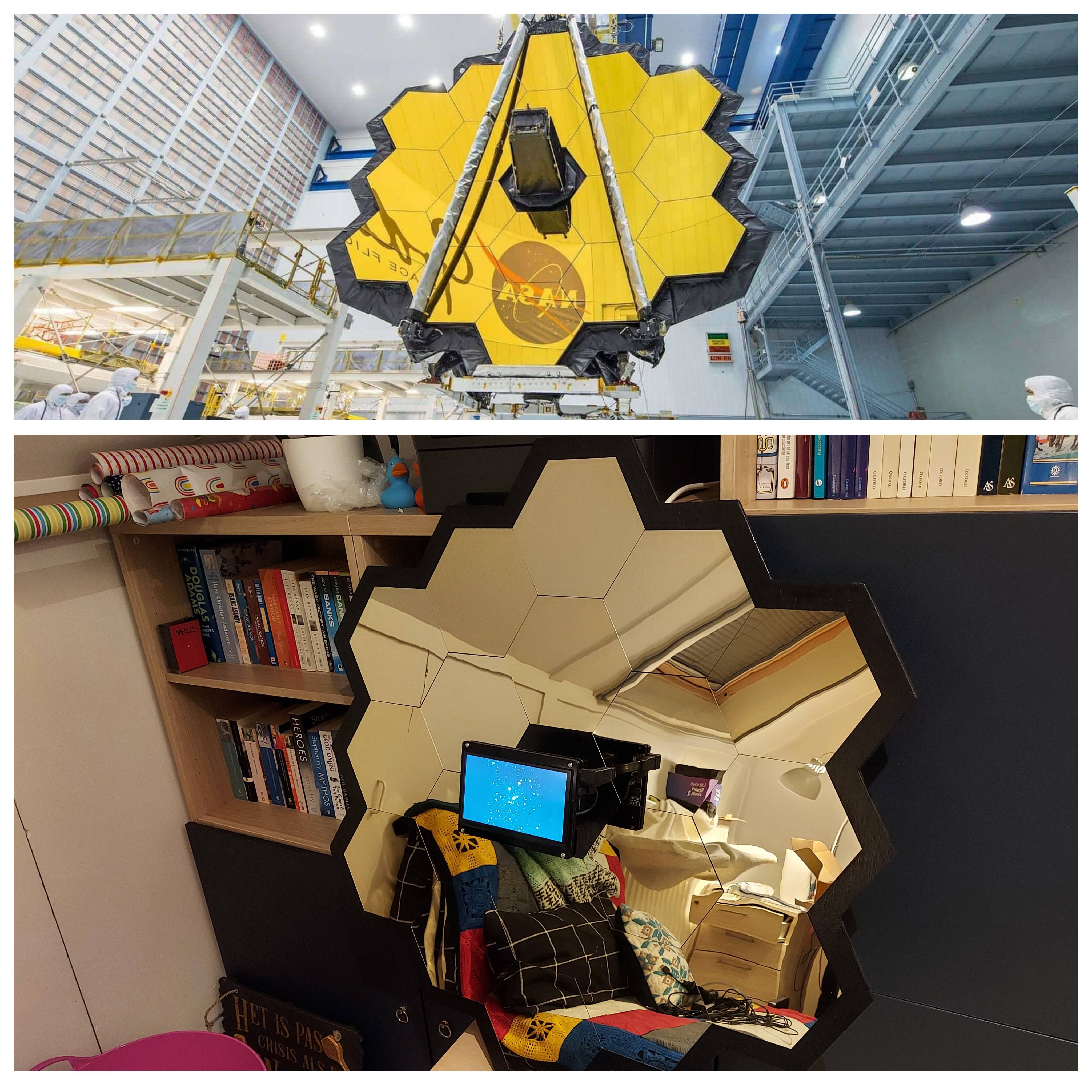
Table of Contents
- Important
- Introduction
- 1. Design
- 2. Raspberry Pi and OS
- 3. Slideshow: fbi and its quirks
- 4. Music: local or online play
- 5. Automation
- 6. DIY and assembly
- 7. When a Plan Comes Together
- Appendix A: Requirements
Important
- I updated this post with current hardware and improvements on 3 august 2025. At the bottom of this post I have listed the requirements in case you want to try this yourself.
- This post details the software side of the project first. If you just want to see how everything was assembled, you can start at chapter 6: DIY and assembly.
Introduction
It was Christmas day 2021 and the James Webb space telescope was launching. Just like many people I know and don’t know, I’m absolutely fascinated by it and I was excited about the images it would produce. Since I’d taken an interest in home automation and building projects, it occurred to me that it would be amazing to have a picture frame in my home somewhere, where I could look at the latest images from the telescope. And then I found gold-coloured hexagonal mirror tiles online.
An idea was born.
So I ordered a bunch, and they were broken. Unperturbed, I ordered another batch.
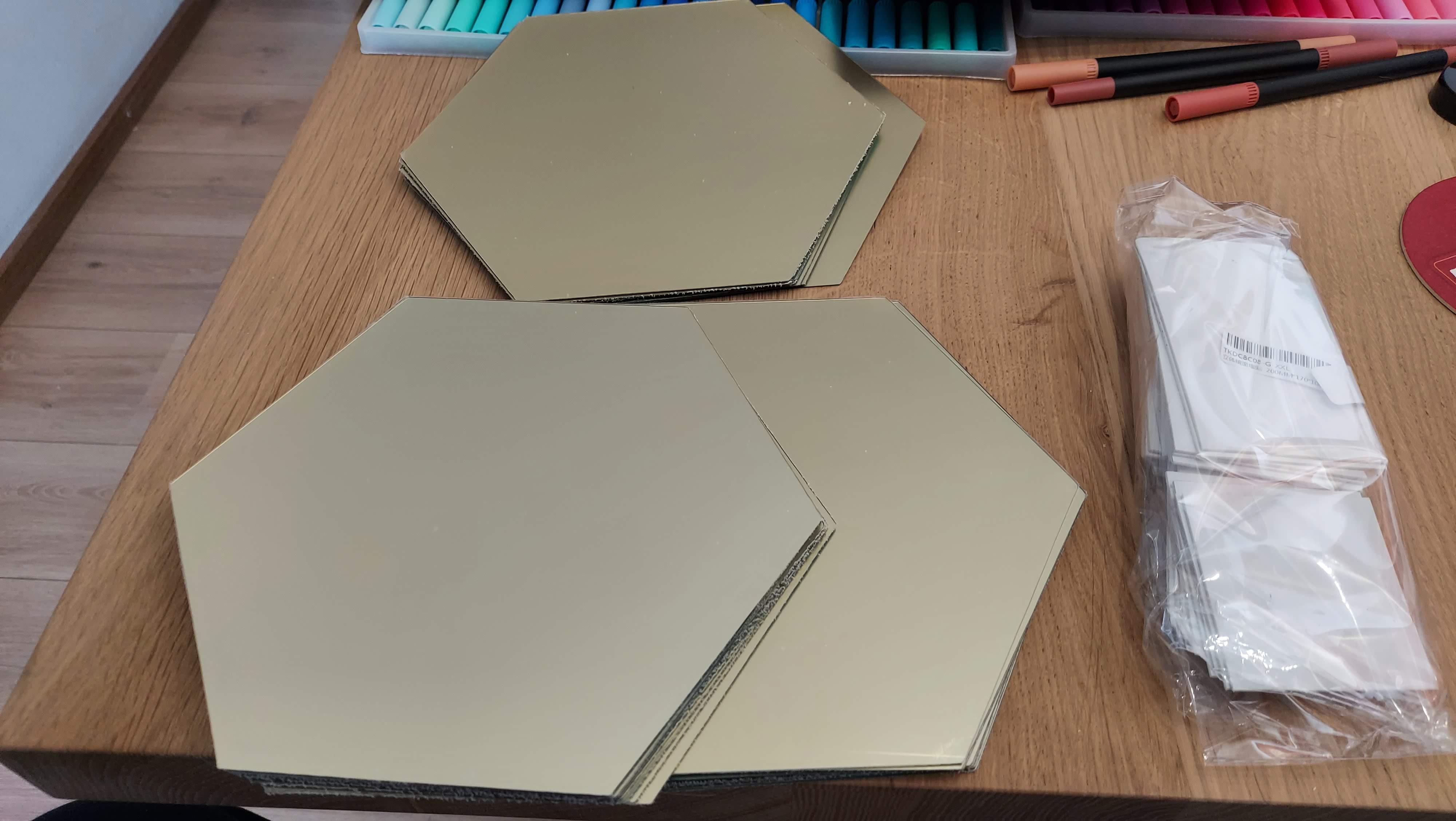 The mirrors
1. Design
Aliexpress takes a while to deliver, so I had time to think about the design. I was going to recreate the idea of the telescope using a wood board, black paint, and these mirrors. In the middle I wanted to put a screen which displays the most recent James Webb images. I made a design:
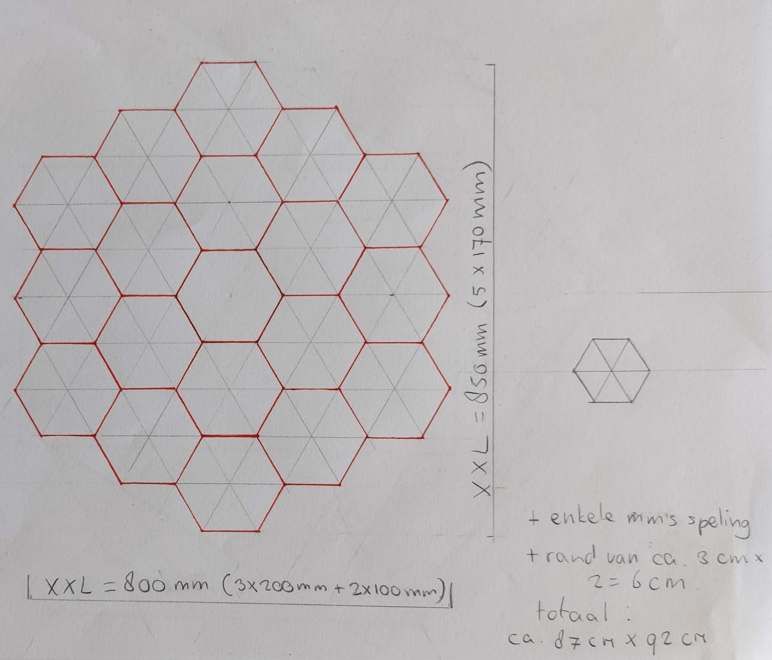 The design and measurements for the board plus mirrors
The middle of the design would contain the display instead of a tile (where the black column is on the actual telescope). I drew one tile in actual size and measured how a screen would fit:
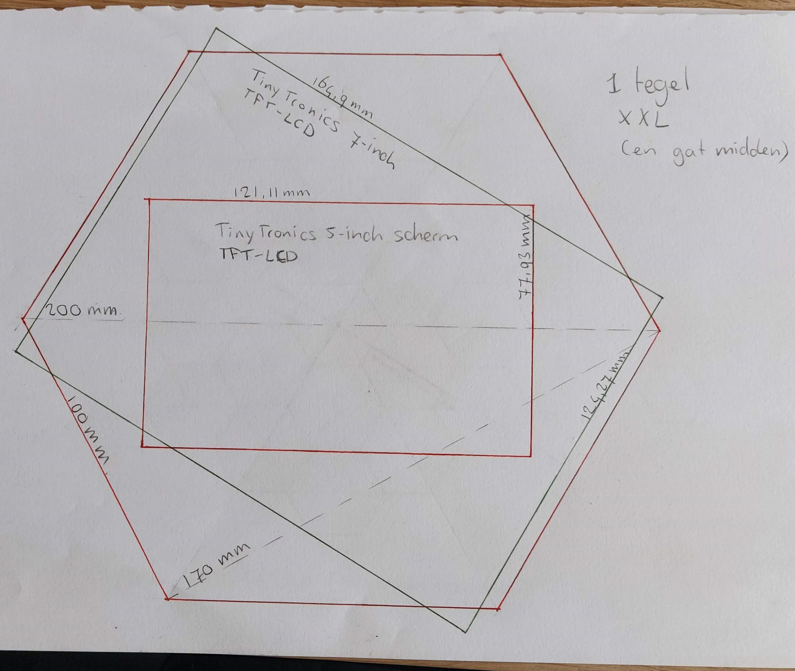 The design and fit of the display
For the display size I had two options in mind: a 5-inch display (the red rectangle inside the hexagon) which seems very tiny and just sad, or a 7-inch display (the tilted green rectangle) which is much better. So I went with the 7-inch one, but this size posed a different problem as it doesn’t fit within one tile-space and thus blocks part of the mirrors from view. I had to solve that, and still keep the design in line with my requirements:
- 7 inch is the minimal size for the display, since on a smaller one the photos would be too small to see properly. I upgraded this to a 10.5-inch display later on, see 6.2. Display.
- All the mirrors around the center should remain intact and visible.
The solution was clear to me: I needed to create a column/cone which attaches to the board (just like on the real telescope!) and contains space to hide the cables. Then I could mount the display on the front of the column.
At this point I started to explain my plans to people, and not a single person understood the way I’d visualised the idea, so bear with me. It will make sense.
2. Raspberry Pi and OS
For the first version I used a Raspberry Pi 3b which I still had lying around. I had wanted to use a Pi Zero 2 W since it takes up less room, but as it turned out the 3b fit behind the board as well. In 2025 I replaced it with a Raspberry Pi 4b, which works much the same.
For the operating system I installed Raspberry Pi OS, which has a very simple installation process you can follow on the Raspberry Pi website. Download the imager, choose the OS you want and write it to the microSD card. A graphic install is optional; I found it useful for first-time setup. I ended up disabling the graphic environment later.
Make sure you can reach your Raspberry Pi via ssh. You can set this up in the configuration before you make the image using the Raspberry Pi Imager. Choose the OS, click on the gear icon in the lower right corner and create a hostname. Then, check Enable SSH and choose whether you want to use a password or a key. Also check Set username and password and fill out those fields. Lastly, you can check Configure wireless LAN and fill out the SSID and password. All of this will save a lot of trouble later on.
If you find that certain functionality isn’t working yet after installation, you can change settings in the config tool which is accessible by typing sudo raspi-config in your terminal. For wifi there’s another handy command line tool you can access by typing sudo nmtui.
Now you can log in to your Raspberry Pi via ssh:
$ ssh username@hostname.local
3. Slideshow: fbi and its quirks
For the slideshow of pictures I’m using the tool fbi - framebuffer imageviewer. This isn’t a perfect tool by far, but I’ve managed to set it up the way I want it. I’m also looking into a different tool called fim (fbi improved). If I end up using that, I will report on it then.
Install fbi using the following commands:
$ sudo apt-get update
$ sudo apt-get -y install fbi
Make sure you have images in a directory somewhere, and start a slideshow using fbi:
$ fbi -T 1 -a -t 300 /path/to/images/*
3.1. Options for fbi
Several required and/or useful command line arguments for fbi are:
-d /dev/fbNuses the /dev/fbN device framebuffer. Default is the one your virtual console is mapped to (fb0in my case). This is needed if you run this command using systemd.-Tstarts fbi on virtual console n, where n is usually 1.--noverbosemakes the info line at the bottom of the screen disappear. Oddly enough, this argument has no effect on the workaround for captions in 3.2. Adding captions with a workaround.-adisplays the images with autozoom, which is great for images of varying sizes.-fdetermines the font type. Font size can be added as well, for example:-f monospace:size=32. This is not officially documented.-tis the interval between slides in seconden.
You can also look at the fbi man page for more info about the options and arguments.
3.2. Adding captions with a workaround
For the specific slideshow I created, I wanted to show a caption below each image. This proved rather difficult to achieve, as fbi does precisely nothing with any annotations, comments, or other info in the exif data of an image, and even if it did, that feature is limited to jpg only. A friend of mine (Peter/Habbie) found out that if you place the image in its own directory and add a .directory file with a desktop entry, fbi picks that up instead and shows the comment in that file (thanks Peter!). This is not officially documented either.
On GitHub I’ve created an example of a directory that will get picked up by fbi: example image directory.
The path to the pictures in the command should contain an extra wildcard so all the directories get added to the slideshow, like so: /path/to/pictures/*/*
This is the command I ended up using:
$ sudo fbi -d /dev/fb0 -T 1 -f monospace:size=32 -a -t 300 /path/to/pictures/*/*
4. Music: local or online play
As I mentioned before, in 2025 I decided to upgrade the project a bit by adding a larger display. The new display I bought happened to have two speakers in the back, perfect for adding some space tunes.
I found two ways of making this happen: locally by installing a player and adding a bunch of mp3 files, or remotely by installing the tool spotifyd, which turns the Raspberry Pi into a Spotify Connect device.
4.1. Local play using mplayer
For local use you can install mplayer like this:
$ sudo apt install -y mplayer
Make sure you have some mp3 files in a directory, and shuffle play the files in a neverending loop:
$ mplayer -loop 0 -shuffle /path/to/mp3/files/*
Of course this can also be achieved using a different media player.
4.2. Remote play using spotifyd
The other option is installing spotifyd. This is not the option I went with, and as this tool has been very well documented, I won’t repeat the instructions here. Check out the GitHub repository for more info.
5. Automation
5.1. Scripts
Of course it would be great if fbi and the media player started up instantly upon booting. To do this, I created two small scripts. For fbi, do this as follows:
$ nano jwst-slideshow.sh
In the script, add the following lines:
#!/bin/sh

    sudo fbi -d /dev/fb0 -T 1 -f monospace:size=32 -a -t 300 /path/to/images/*/*
Of course you should edit the fbi command arguments to your liking and change the directory. Save your changes with Ctrl+O and exit nano with Ctrl+X. Make your script executable with:
$ sudo chmod +x jwst-slideshow.sh
For a local music player, make another script containing the command you use to play the music files.
5.2. Systemd
Next, add your script to a systemd service file. Create a .service file:
$ sudo nano /etc/systemd/system/jwst-slideshow.service
and add the following lines to it, replacing ‘user’ with your username and adding in the correct path to the script after ‘ExecStart’:
[Unit]
Description=Systemd service for starting the JWST slideshow
After=multi-user.target

[Service]
Type=exec
User=user
ExecStart=/path/to/jwst-slideshow.sh --no-daemon
RemainAfterExit=true
Restart=always
RestartSec=60

[Install]
WantedBy=default.target
Make your service executable:
$ sudo chmod 644 /etc/systemd/system/jwst-slideshow.service
end then activate the systemd service:
$ sudo systemctl enable jwst-slideshow.service
You can do the same for the media player script, which needs one extra line under [unit]: Wants=sound.target. I’ve put some example .service files on GitHub.
Reboot your Raspberry Pi, and you’re set!
Next up: DIY all the things.
6. DIY and assembly
Of course you can start the DIY immediately, but it’s good to note that testing the hardware and software before putting everything together is a must. The project is very wieldy and you don’t want to pull a muscle trying to look up at a wall while you’re testing.
6.1. Wooden Board
My dad is a retired carpenter, so I asked him if perhaps he had a wooden board lying around that was large enough for the project, and he did! I drew the outline of the mirrors on the board and then I made a 3cm edge around it. Larger would have been fine too, but I was worried about the massive size of the project so I kept it modest.
My dad did most of the sawing since that really isn’t my strong point. I would have messed it up for sure. He also drilled a large hole in the middle for the cables.
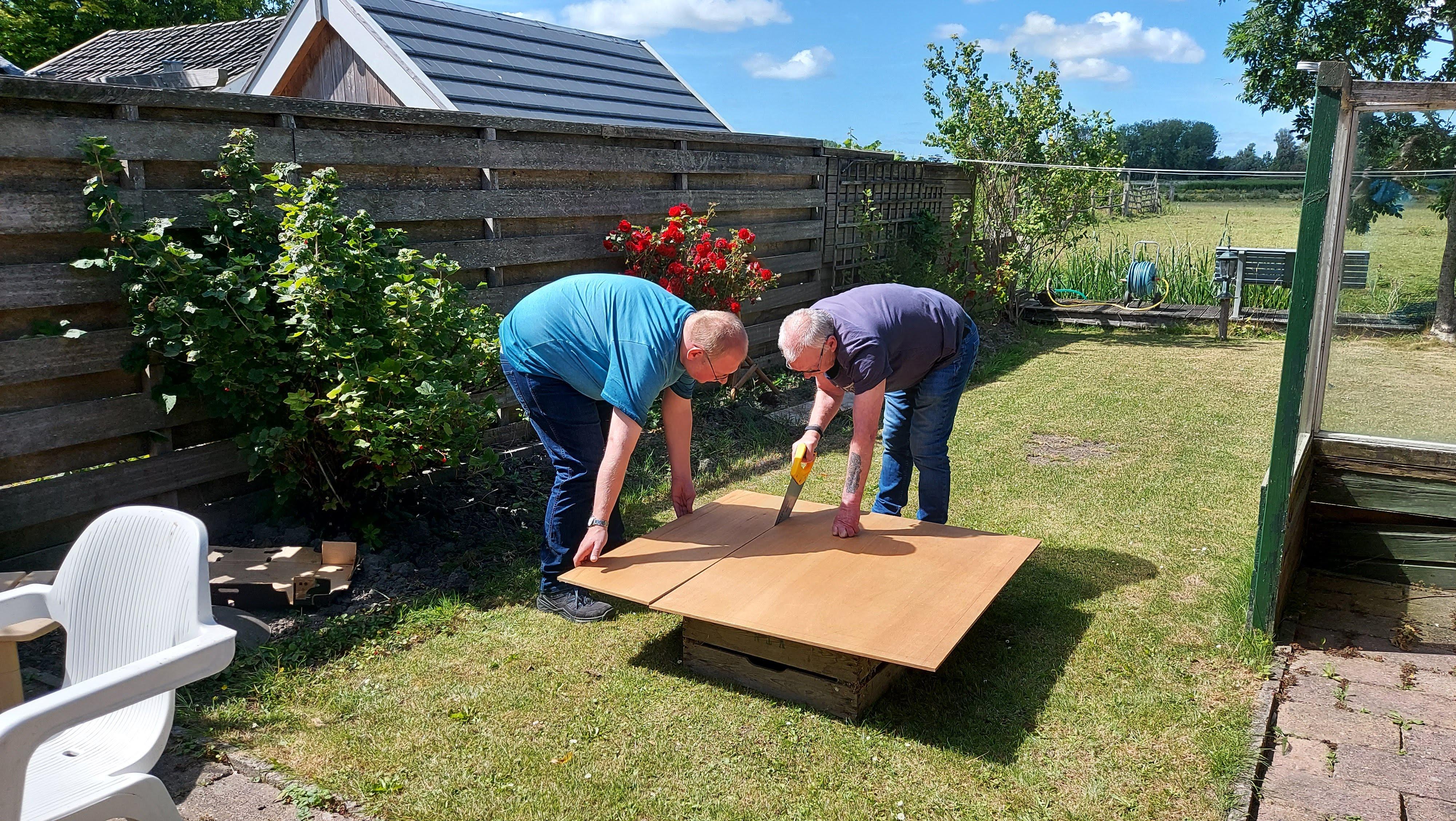 My dad sawing and my brother helping out. Love you dad and Frank! ❤️
My brother and I sanded the board, especially around the edges to make them rounder. I took the board home and after using some wood filler on a few irregularities I painted it black, adding three layers of paint just to be sure.
 Painting the board black
6.2. Display
I started with a 7-inch display, which I later replaced with a 10.5-inch display from Aliexpress (for links, see Requirements). The new display has holes in the back for a 75x75mm VESA bracket and it has two speakers in the back.
6.3. Column
Of all the DIY I did, the column was probably the biggest challenge. I designed a rudimentary column in Tinkercad and bought a 3D print. It was quite a gamble and it could have gone very wrong, but it worked out well for the first version. I upgraded the design when I got a 3D printer.
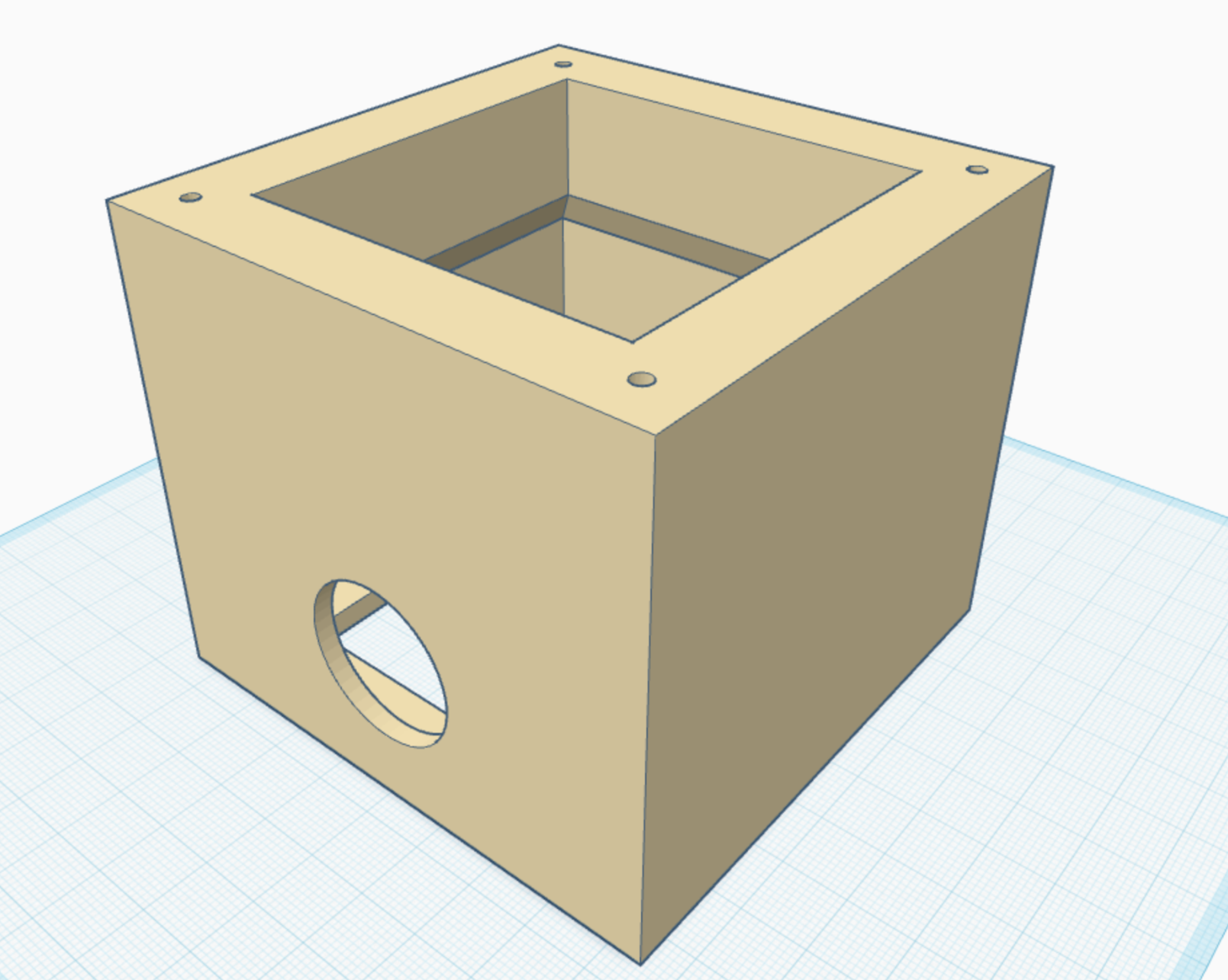 Design in Tinkercad
The design has screw holes on both sides, which both fit the 75x75mm VESA standard. On the board side the screw holes are not very deep, so a sharp-pointed screw will work itself into the PLA for a strong hold. On the display side, I ended up only using the screws that came with the VESA bracket I bought.
Note: the column has a hole for the cables in one side, so be sure to mount it with the hole on the correct side.
On GitHub you can find the stl and a link to Tinkercad there in case you want to edit the source file.
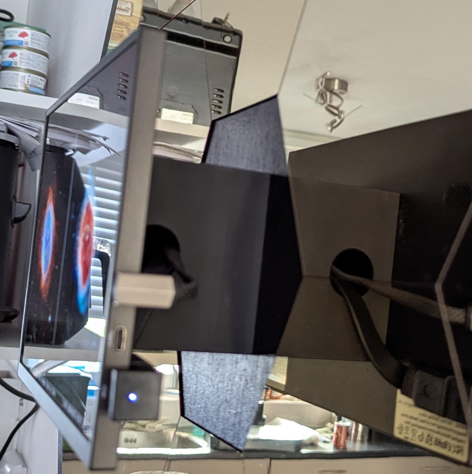 The column with the display attached to it
6.4. Back Side and Mirrors
On the back of the board there was still a lot of work to do. I started by attaching two small wooden bars: one as a wall mount and one for balance. On the top bar, I installed two hooks using two screws each, so they’re fixed very securely and can take a lot of weight.
I also screwed the Raspberry Pi onto the board at this point, making sure that the ports were facing the right way so the cables are easy to attach and route. The Raspberry pi is in a 3D-printed case, which I will link in the Requirements.
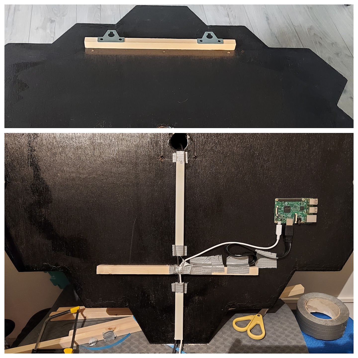 Hooks and cable management on the back side
At this point the screen/column unit needed to be attached to the center of the board. I started by drilling 4 holes in the board, which I had carefully measured out using the 75x75mm VESA standard so the whole thing would end up exactly in the center. Then I used sharp-pointed screws to securely fix the unit to the board.
Connectors with 90 degree corners hide the cables, which have been fed through the hole in the column and come out of the hole in the center of the board. Using a leftover piece of cable duct (and duct tape where needed), I routed the cables to the Raspberry Pi and down to the bottom center of the board. Here I forgot to make room for the cables in the bottom wooden bar. I fixed that by removing some wood with a hammer and a chisel (very, very carefully because of the display). Of course other solutions would be better, such as two smaller bars.
7. When a Plan Comes Together
The last DIY part was attaching the mirrors, which I did using the supplied round pieces of double-sided tape. I actually added them a little earlier in the process because I got impatient, but I highly recommend adding them at the absolute latest moment since they scratch and break easily. It ended up fine in my case, but you know how these things can go. The size of the mirrors wasn’t always perfect so it was quite a puzzle, but it still looks great!
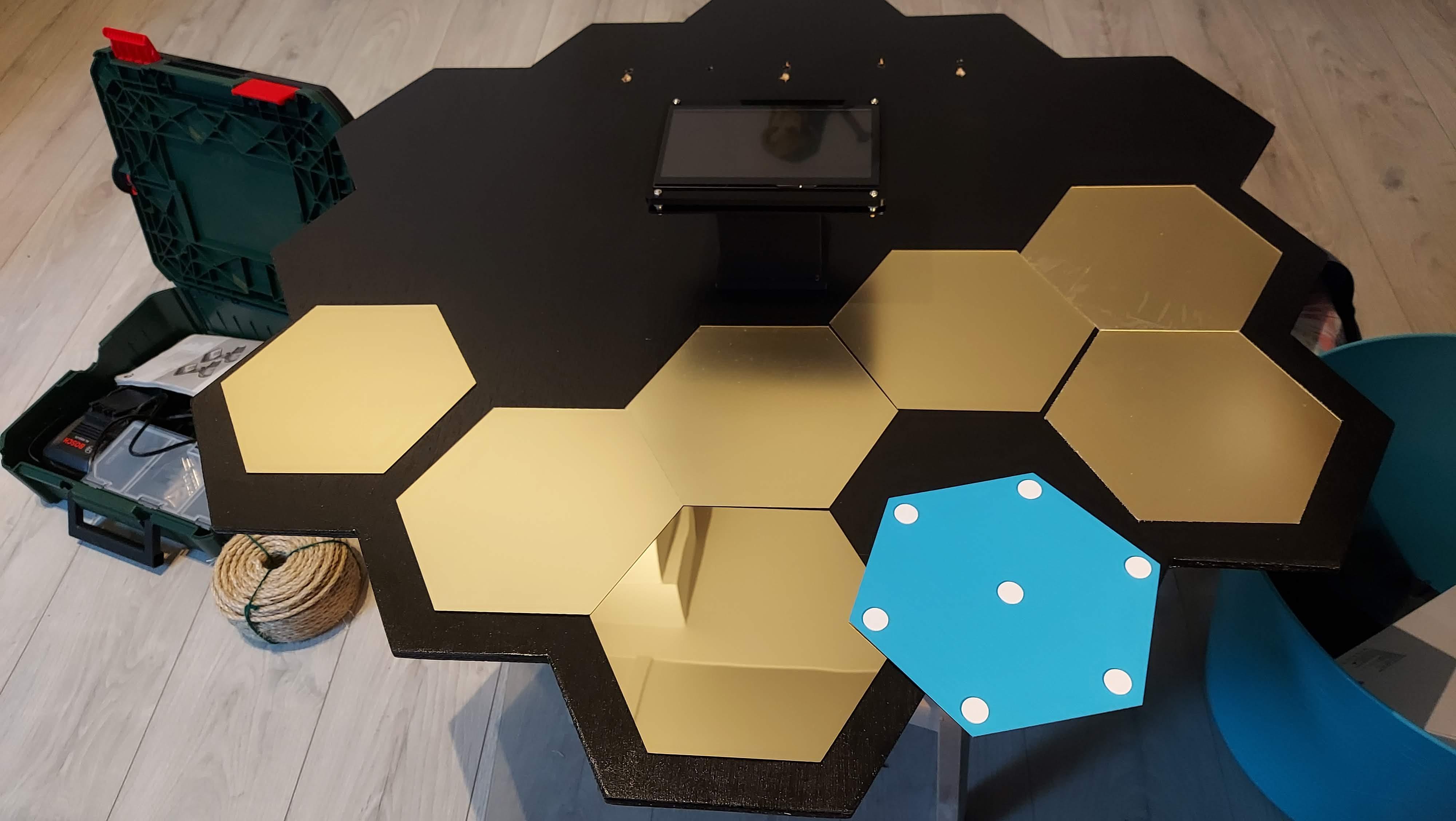 The mirror puzzle 🧩
And then, finally, the reveal. I couldn’t be happier with the result!
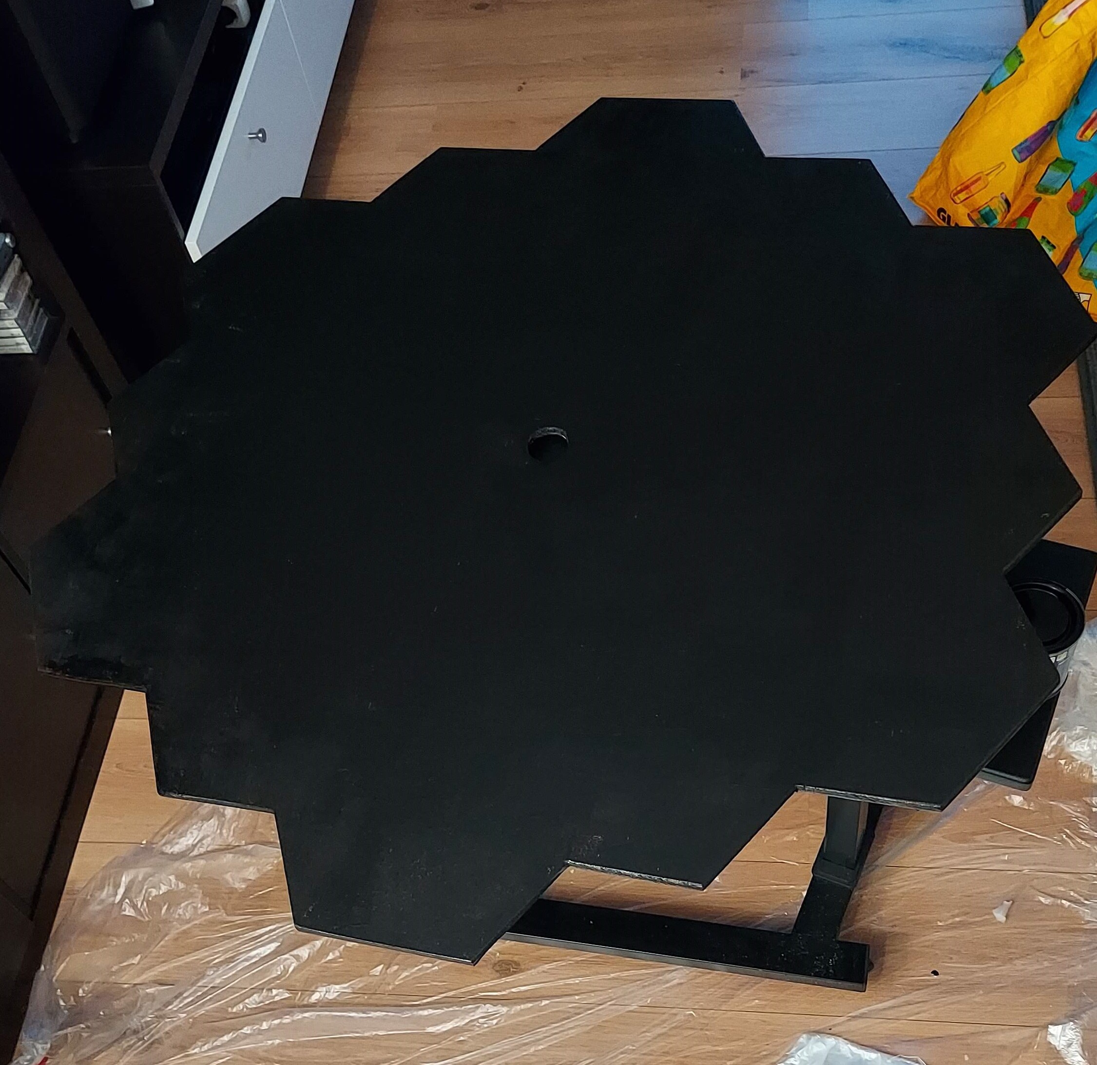
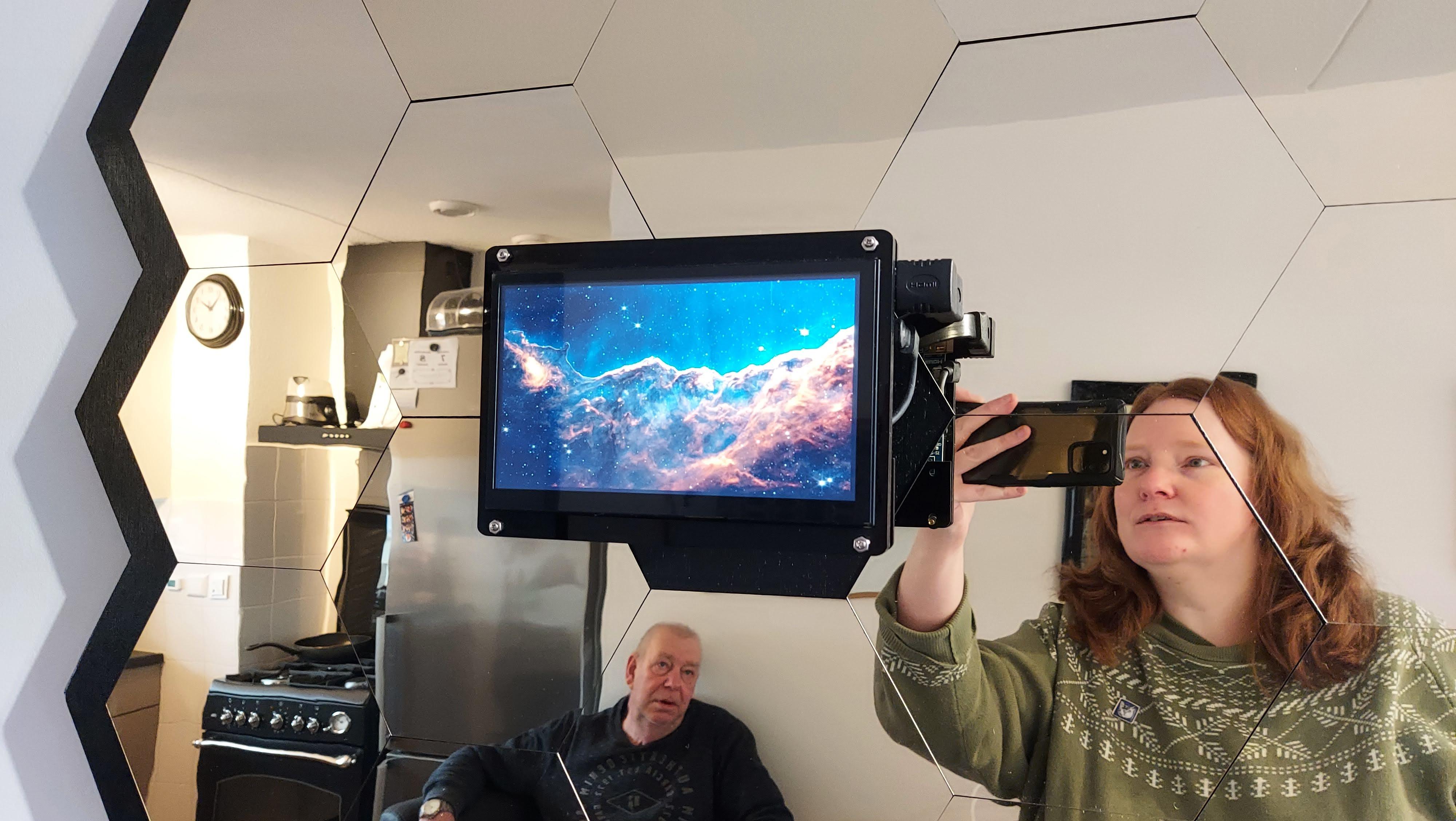 Version 1, featuring my dad and myself in the mirrors
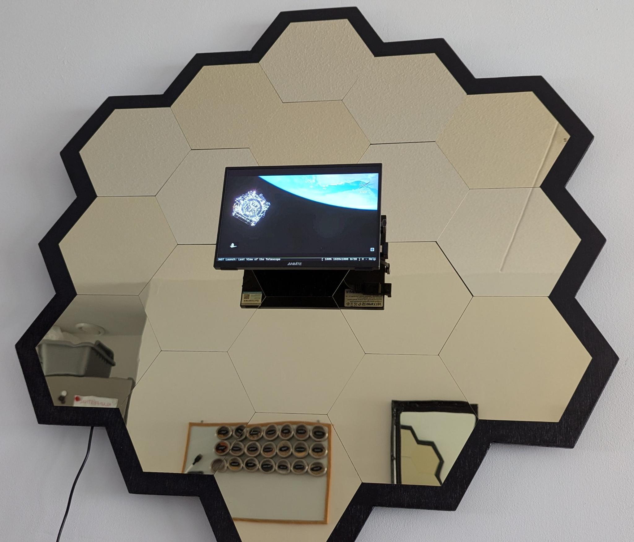 Version 2, now with a larger screen
And check out the music on YouTube:
The slideshow in action, with musicLots of thanks to my dad, my brother and a bunch of nerds on irc. I’m absolutely over the moon and straight into L2 with this ❤️
Appendix A: Requirements
A.1. DIY hardware
- 18 hexagonal mirror tiles. Find them on Aliexpress: mirror tiles. Order extra, they break easily!
- A large board of wood.
- Wood filler for holes/irregularities in the wood.
- Black paint and painting supplies.
- A wooden bar (to divide in one longer piece and two shorter pieces).
- A 3D-printed column.
- A 3D-printed case for the Raspberry Pi - link
- A piece of thin cable duct.
A.2. Computer hardware
- A 10.5-inch display. Find it on Aliexpress: display, or search for ‘10.5 inch monitor’
- A 75x75mm VESA bracket. Find it on Aliexpress: VESA bracket, or search for ‘75mm VESA bracket’. I ended up only using the screws.
- A HDMI cable and adapter for the screen. I used cables with angled adapters on the display side so they wouldn’t stick out.
- A Raspberry Pi with an RPi adapter. Other adapter brands are possible, but they often don’t play well with the voltage the Raspberry Pi requires. I mentioned using a 3b/4b instead of a Zero 2 W, but if you have a Raspberry Pi Zero that works just fine, since fbi doesn’t create a heavy load. I haven’t tested this with the additional media player functionality though.
- A microSD card. I used a 64GB card but smaller is absolutely fine.
A.3. Software
- Raspberry Pi OS.
- fbi, a slideshow tool for Linux.
- mplayer if you want to play mp3 music.
- spotifyd if you want to add a Spotify playlist.
- You can find the following files on my GitHub repository:
- the .stl file for the column
- two example scripts for the fbi slideshow and the media player
- two example .service files for systemd
- an example folder containing an image and a .directory file